
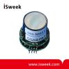
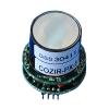
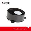
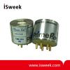
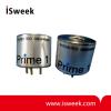
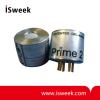
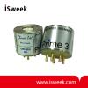
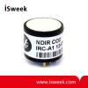
Probe Type NDIR CO2 Sensor - COZIR-Probe
• Ultra-low Power 3.5mW
• Measurement ranges from 5% to 100%
• Accuracy: ±70 ppm +/- 5% of reading
• 3.3V supply.
• Peak current only 33mA.
• Optional Temperature and Humidity Output
- Model Number: COZIR-Probe
- Data Sheet:

- Quantity:
- - +


Product Specification
Probe Type NDIR CO2 Sensor Carbon Dioxide Sensor Summary
COZIR series is an ultra low power (3.5mW), high performance CO2 sensor, ideally suited for battery operation, portable instruments or solar powered applications. Based on GSS IR LED and Detector technology, and innovative optical designs, the COZIR offers the lowest power NDIR sensor available. COZIR is a third generation product from GSS - leaders in IR LED CO2 sensing.
• Ultra-low Power 3.5mW
• Measurement ranges from 5% to 100%
• 3.3V supply.
• Peak current only 33mA.
• Optional Temperature and Humidity Output
Probe Type NDIR CO2 Sensor Carbon Dioxide Sensor Specifications
|
General Performance |
|
|
Warm-up Time |
< 10s |
|
Operating Conditions |
0°C to 50°C (standard) -25°C to 55°C (extended range) 0 to 95% RH, non-condensing |
|
Recommended Storage |
-30°C to +70°C |
|
CO2 Measurement |
|
|
Sensing Method |
Non-dispersive infrared (NDIR) absorption Patented Gold-plated optics Patented Solid-state source and detector |
|
Sample Method |
Diffusion |
|
Measurement Range |
0-5%,0-20%,0-60%,0-100% |
|
Accuracy |
±70 ppm +/- 5% of reading |
|
Non Linearity |
< 1% of FS |
|
Pressure Dependence |
0.13% of reading per mm Hg in normal atmospheric conditions. |
|
Operating Pressure Range |
950 mbar to 10 bar |
|
Response Time |
4 secs to 2 mins (user Configurable) Reading refreshed twice per second. |
|
Electrical/Mechanical |
|
|
Power Input |
3.2 to 5V. (3.3V recommended). Peak Current 33mA Average Current <1.5mA |
|
Power Consumption |
3.5 mW |
|
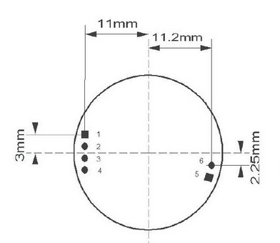
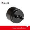
Dimensions and Wiring Connections |
4*12mm header. 2*12mm header(NC) |
|
Function |
Pin # |
X |
Y |
|
0V |
1 |
-11.0 |
3.0 |
|
+3.3V |
2 |
-11.0 |
1.0 |
|
Sensor Rx |
3 |
-11.0 |
-1.0 |
|
Sensor Tx |
4 |
-11.0 |
-3.0 |
|
N2 Zero |
5 |
10.64 |
-4.18 |
|
N/C |
6 |
11.2 |
-2.25 |
This shows the position of the connectors looking from above the sensor. ie this is the corrcet pattern for a mating PCB.
If you cannot find what you want, you can entrust ISweek to source for you. Just click:
Sourcing ServiceRecommended Products
-
Ultra Low Power Digital Output NDIR CO2 Gas Sensor
-
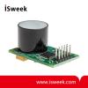
Ultra Low Power Carbon Dioxide Sensor NDIR CO2 Sensor
-
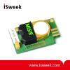
Low Cost HVAC Carbon Dioxide Sensor NDIR CO2 Sensor
-
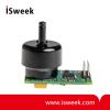
High Speed Carbon Dioxide Sensor NDIR CO2 Sensor 20Hz 0-100%
-
Infrared Gas Sensor for Oil Industry Methane Sensor
-
High Resolution Infrared Methane (CH4) Sensor
-
Voltage Output Infrared Carbon Dioxide (CO2) Gas Sensor
-
Voltage output Infrared Carbon Dioxide (CO2) Gas Sensor
-
Infrared Carbon Dioxide (CO2) Sensor Pyroelectric Detector
-
Fast Response NDIR CO2 Sensor Carbon Dioxide Sensor