
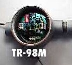
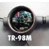
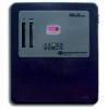
Transmitter Relay Contact - TR-98M
• Relay Specifications: Single-Pole, Double-Throw, 5A at 117VAC resistive.
• Optional Connections: Using a jumper connection, the TR-98M gives the user the option to have the relay operate in either Normal or Fail-Safe mode.
• Normal mode: The relay makes contact as the signal reaches the set point and turns off when the alarm condition disappears.
- Model Number: TR-98M
- Quantity:
- - +
Mouse over image to zoom
Product Specification
TRANSMITTER RELAY CONTACT: TR-98
 General
Sensor transmitters typically provide a 4-20 mA output, and this signal can be fed to a controller which provides alarm processing and relay contacts to trip alarm horns/lights, activate ventilation motors, etc. However, some applications require relay contacts to be located at the sensor transmitter itself. For these applications, the TR-98M Transmitter Relay provides a simple solution. Even though it is designed for IST transmitters, it will also work with other transmitters which produce a 4-20 mA signal.
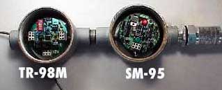
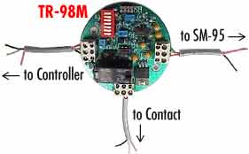
The TR-98M (master) incorporates a conduit fitting which enables it to attach directly to either the SM95 or 4-20IQ transmitter, and provides one Single-Pole Double-Throw (SPDT) relay contact. A seven segment DIP switch allows you to program the relay to trip at a designated value within the 4-20 mA signal range. If additional relay contacts are needed, the TR-98S (slave), a slave relay module, can be added. Up to four TR-98S units can be added, providing a total of five relay contacts.
Both the TR-98M and TR-98S are housed in explosion-proof enclosures rated for use in Class 1, Division 1, Groups B,C and D hazardous areas.
Setting the Alalrm Set Point
1 = 1%, 2 = 2%, 3 = 4%, 4 = 8%, 5 = 16%, 6 = 32%, and 7 = 64%
Switch positions are clearly marked on the DIP switch package.
The alarm set point is the sum of the values in the OPEN position. For instance, for an alarm set point of 20% of full scale, switches 3 and 5 should be in the OPEN position while the rest of the switches should be closed. This yields S3 (4%) + S5 (16%) = 20%. With a 4-20 mA output, this would mean an alarm set at 7.2 mA.
Relay Specifications
Single-Pole, Double-Throw, 5A at 117VAC resistive.
Optional Connections
Using a jumper connection, the TR-98M gives the user the option to have the relay operate in either Normal or Fail-Safe mode.
Normal mode: The relay makes contact as the signal reaches the set point and turns off when the alarm condition disappears.
Fail-Safe mode: The relay is energized at all times. The relay is de-energized (activated) if the signal reaches the alarm set point or if there is a 24VDC power failure. Since relays are always energized, this configuration consumes more power. Note also that relay output connections are reversed, so that Normally Open connections become Normally Closed.
Unless specified, all TR-98 modules are shipped with relays in Normal mode.
If you cannot find what you want, you can entrust ISweek to source for you. Just click:
Sourcing ServiceRecommended Products
-
Flexible Sampling System
-
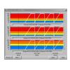
8+ Channels Computerized Remote-Link System
-
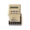
Programmable, Multifunction Digital Time Delay Relay
-
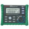
Digital Earth Resistance Tester
-
Advanced Earth Resistance Tester
-
Analog Earth Resistance Tester
-
Digital Insulation Tester
-
High Voltage Insulation Tester
-
Digital Insulation Tester
-
High Voltage Insulation Tester