
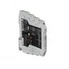
electricians Set-Point Alarm Relay BasicLine - BL 550
The configurable threshold value switch is used to control and monitor analog standard signals.
- Model Number: BL 550
- Data Sheet:

- Quantity:
- - +
Product Specification
1. Safety notes
1.1 Installation notes
• Installation, operation, and maintenance may only be carried out by qualified electricians. Follow the installation instructions as described. When installing and operating the device, the applicable regulations and safety directives (including national safety directives), as well as generally approved technical regulations, must be observed. The safety data is provided in this package slip and on the certificates (conformity assessment, additional approvals where applicable).
• The device must not be opened or modified. Do not repair the device yourself, replace it manufacturer is not liable for damage resulting from violation.
• The IP20 protection (IEC 60529/EN 60529) of with an equivalent device. Repairs may only be carried out by the manufacturer. The the device is intended for use in a clean and dry environment. The device must not be subject to mechanical strain and/or thermal loads, which exceed the limits described.
• This device is not designed for use in potentially explosive atmospheres.
• When installing the device, use an appropriate housing with a minimum protection of IP54.
• Only snap the device onto or off the DIN rail connectors and connect/disconnect cables when the power is disconnected.
• The device must be stopped if it is damaged, has been subjected to an impermissible load, stored incorrectly, or if it malfunctions.
2. Short description
The configurable threshold value switch is used to control and monitor analog standard signals. On the input side, the 0...10 V or 0...20 mA standards signals canbe selected.
A high-quality PDT relay with a gold layer is located on the output side. It can be operated in both operating current and closed circuit current behavior.
The DIP switches are accessible on the side of the housing and allow the following parameters to be configured:
Input signal, switching hysteresis, operating direction (operating current and closed circuit current behavior), relay pickup/relay dropout delays.
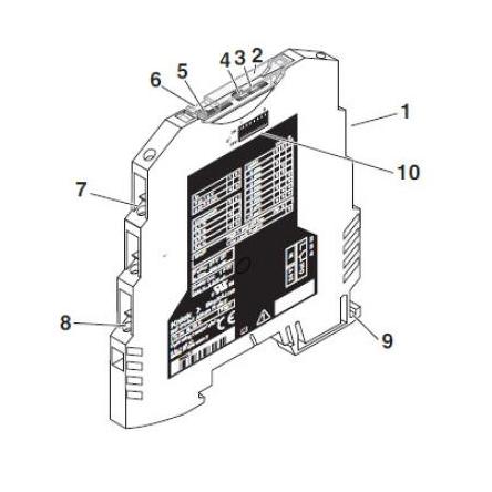
3 Operating elements
1 Relay output
2 Cover
3 Yellow LED: Status indication
4 Red LED: Error messages
5 Potentiometer for setting the switching thresholds
6 Groove for ZBF 6 zack marker strip
7 Input: Standard signals
8 Supply voltage
9 Universal snap-on foot for EN DIN rails
10 DIP switch S1
If you cannot find what you want, you can entrust ISweek to source for you. Just click:
Sourcing ServiceRecommended Products
-
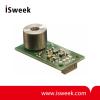
Thermopile Infrared Temperature Sensor Module
-
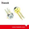
Infrared Thermopile Temperature Sensor
-
Assembled Armored Platinum Resistor
-
Armored Thermocouple
-
“ZERO DRIFT” High Accuracy Integrated Temperature Transmitter
-
“ZERO DRIFT” High Accuracy Thermocouple Integrated Temperature Transmitter
-
Humidity and Temperature Sensor
-
Digital Humidity and Temperature Sensor with 3V Supply Voltage
-
Digital Humidity and Temperature Sensor with 5 V Supply Voltage
-
BasicLine BL 520 Temperature Transmitter