
Relative Humidity and Temperature Sensor with I²C Interface - ENS210
The ENS210 applications include:
• Building Automation / Smart home / HVAC1
• Home appliances
• Mobiles / Wearables
• IoT devices
• Portable devices for personal health and wellness
• Weather stations
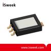
- Model Number: ENS210
- Data Sheet:

- Quantity:
- - +

Product Specification
ENS210 General Description:
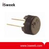
The ENS210 integrates one relative humidity sensor and one high-accuracy temperature sensor. The device is encapsulated in a QFN4 package and includes an I²C slave interface for communication with a master processor.
ENS210 Key Benefits and Features:
The benefits and features of ENS210, Relative Humidity and Temperature Sensor with I²C Interface are listed below:
|
Benefits |
Features |
|
Ultra-accurate |
• Temperature sensor (±0.15°C) • Relative humidity sensor (Typ:±2.0%RH) |
|
Wide sensing range |
• Temperature operating range (–40°C to 100°C) • Relative humidity operating range (0% to 100%) |
|
Wide operating voltage |
• 1.71V to 3.60V |
|
Small foot-print |
• 2.0mm x 2.0mm x 0.75mm |
|
Industry standard two-wire interface |
• Standard (100kbit/s) and fast (400kbit/s) I²C |
|
Low power |
• Automatic low-power standby when not measuring • Active current: 6.6μA @ 1Hz (1.8V) • Standby current: 40nA |
|
Cost effective |
• Digital pre-calibrated relative humidity and temperature sensor • Output directly in %RH and Kelvin • Wide supply voltage range |
|
High reliability |
• Long-term stability |
ENS210 Applications:
The ENS210 applications include:
• Building Automation / Smart home / HVAC1
◦ Indoor air quality detection
◦ Demand-controlled ventilation
◦ Smart thermostats
• Home appliances
◦ Air cleaners / purifiers
◦ Refrigerators, washing machines, dishwashers, dryers
• Mobiles / Wearables
• IoT devices
• Portable devices for personal health and wellness
• Weather stations
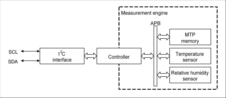
ENS210 Block Diagram:
The internal block diagram of ENS210 is shown in Figure 2. The I²C (communication) interface is connected to a controller which acts as the command interpreter and as bus master of the internal Advanced Peripheral Bus (APB). The memory and sensors are slaves of the APB. The MTP memory is used to store the sensor calibration parameters and unique ID.
To reduce power consumption the controller only powers the measurement engine when needed.
If you cannot find what you want, you can entrust ISweek to source for you. Just click:
Sourcing ServiceRecommended Products
-
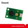
Miniature Digital Relative Humidity and Temperature Sensor
-
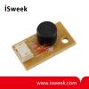
Probe Style Relative Humidity Sensor Module
-
Capacitive Humidity Sensor
-

Voltage Output Temperature and Humidity Sensor
-
Humidity and Temperature Sensor Module
-
Voltage Output Humidity and Temperature Sensor Module
-
Voltage Output Temperature and Humidity Sensor
-
Temperature Humidity Sensor Module
-
Frequency Output Temperature and Humidity Sensor
-
Capacitive Temperature and Humidity Sensor